
The Kanzaki gearboxes used by Yanmar use a ‘wet’ cone clutch, in which the cone, together with the gears and the bearings, all run in an oil-splash environment. When this starts to slip, the internet usually suggests grinding the contact surfaces together with valve paste. (One alternative suggestion was to run the gearbox with diesel instead of gear oil.) There is, however, a much better and safer solution.
The drive cone surface is covered with concentric ridges, separated by grooves. If you run your fingers across the ridges along the axis of the cone, they should feel rough. In a worn cone, the ridge tops are flattened off and this roughness is absent. The repair consists of having the grooves re-cut. This narrows the ridges, making them sharper, and deepens the ridges, which helps the oil to displace from the concave contact surfaces in the gears.
The cost of a new cone can be of the order of £1,000, so it is quite a saving if you can find a specialist engineering firm that know how to do the re-cutting. I used Bakker Ijlst, in the Netherlands (www.bakker-ijlst.nl) who charged 115 Euros + VAT. They can also supply the left-handed castellated nuts that a gearbox rebuild my require. Incidentally, they recommend single-grade SAE30 gear oil for the gearbox.
Below is a summary of the way that the cone clutch operates.
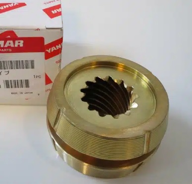
A brand-new, shiny and grippy cone clutch. There are several different models and- if you buy one- you need to be certain that you are getting the exact one for your gearbox.
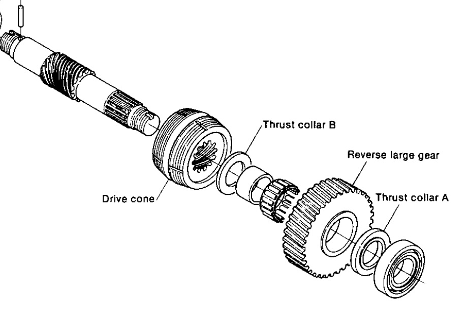
The cone is a component of the output shaft. It can be shifted forward or backward along the shaft, running on a helical gear along the shaft axis, but the shaft will always turn if the cone is turning at one end or the other of the helical gear on the shaft.
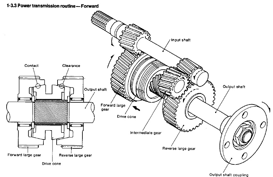
The large forward and reverse gears (and the reverse intermediate gear) turn all the time when the engine is running. The cone is moved along the output shaft to engage with the inside concave drive surface of one or the other gear. The helical gear that the cone rides on help to throw the cone into a positive contact. In this image, the cone engages with the forward gear and the output shaft is therefore rotates with the cone. The reverse gear is still turning, but idles on the shaft.
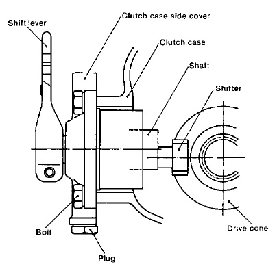
This is the shifting mechanism, viewed along the axis of the output shaft. The ‘shifter’ itself is a key with bearing surfaces, which engages with the large groove around the centre of the cone. As the ‘shifter’ is off-axis, partial rotation of the shift lever causes the ‘shifter’ to move parallel to the shaft, which moves the cone into engagement with one or the other gear.

