
The prop shaft alignment can be checked whenever the gearbox and prop shaft flanges are separated. It is essential after fitting new engine mounts- and again after 50 hours of operation
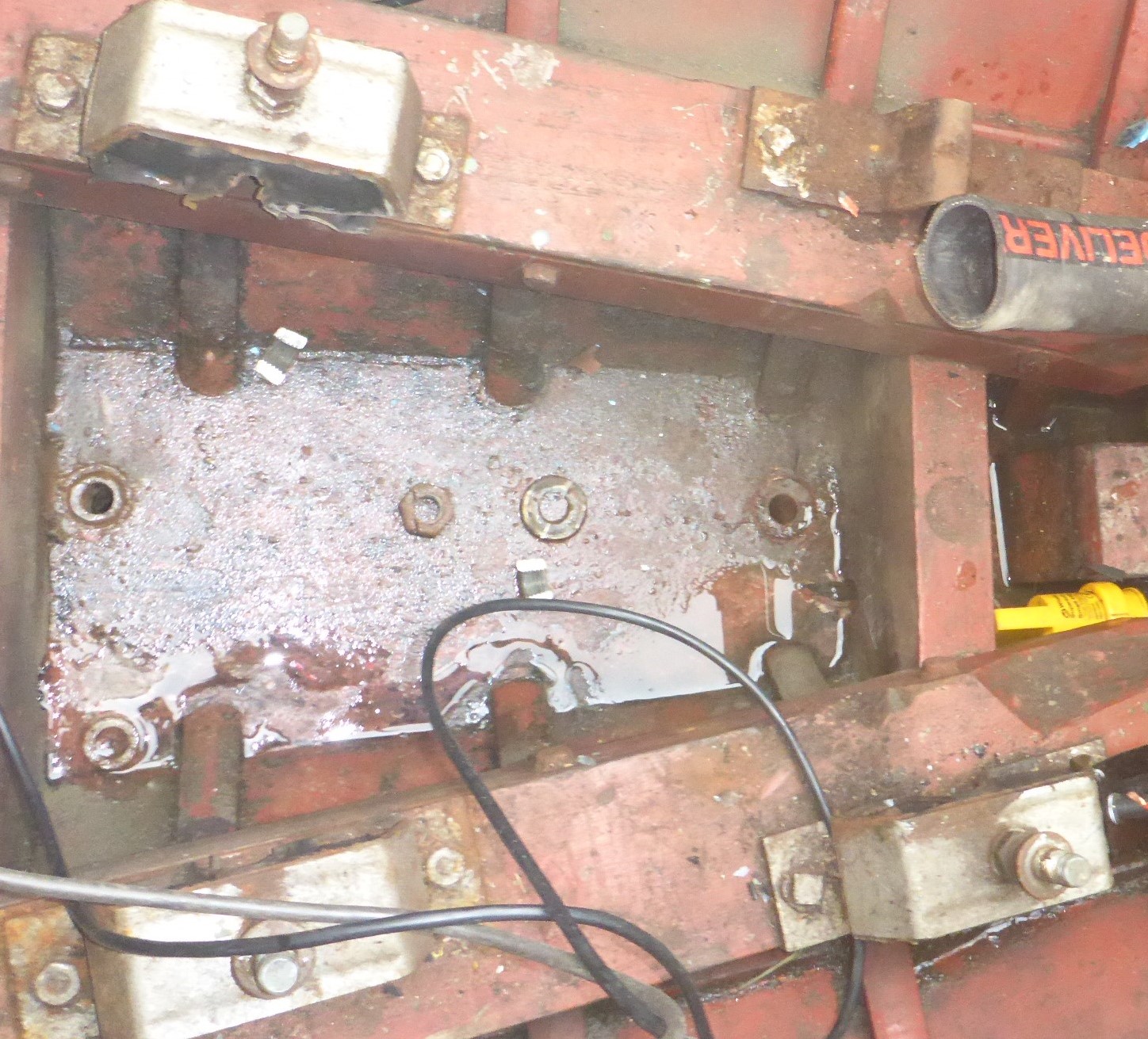
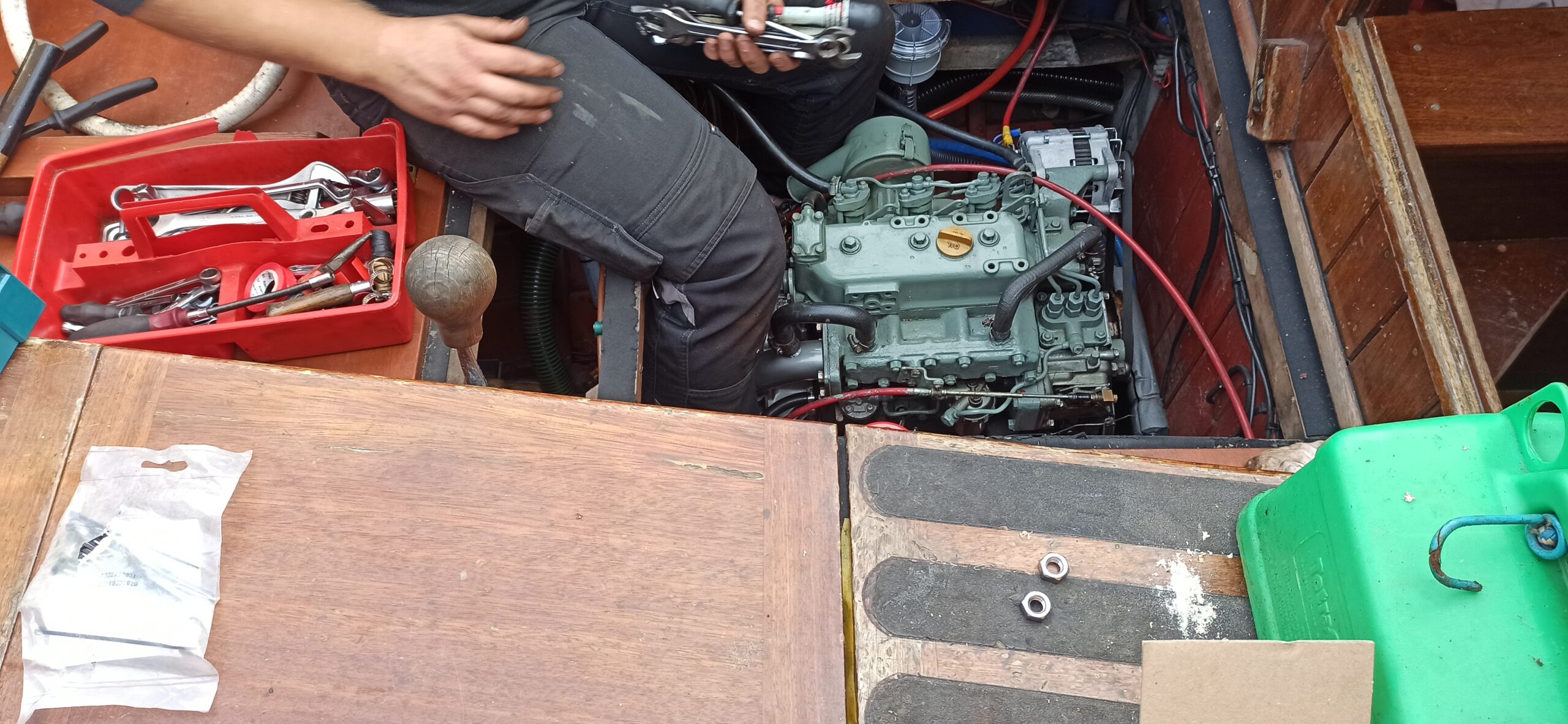
One of these old rubber mounts was found to be no longer bonded to its base plate when the engine was removed for access to the keel bolts. All the mounts were replaced
If your engine has been in place since the year dot, the alignment between the gearbox and prop shaft flanges won’t be keeping you awake at night.
However, what if your old engine mounts are no longer up to the job and you decide to replace them? Or maybe you have replaced the gearbox or the cutlass bearing? If the gearbox and propshaft flanged have been parted, the alignment between the two should be checked on reassembly.
In addition, if the mounts have been replaced, the alignment needs to be re-checked after the first 50 hours of operation (just like when a new engine is fitted) as the rubber compound settles over time.
The alignment procedure can be quite straightforward if the the nuts and bolts are free to
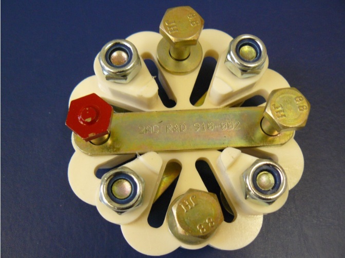
R&D flexible coupling. Measure the spacing between the opposite bolts to check the size- I used product 910-002 with a 4 inch diameter. Available from www.sillette.co.uk
turn. Consider replacing the flexible coupling; not only will the fastenings behave themselves, but also a new R&D coupling has a special bolt (painted red) which is used to check the alignment with a feeler gauge.
First phase
In the first phase of alignment, bolt the coupling to the prop flange only, with the red bolt head facing forward (towards the gearbox). The alignment needs to be good enough for the four gearbox flange bolts (captured in the flexible coupling) to pass easily through their respective holes in the gearbox flange. Aim for minimal interference as the bolts as you move the prop shaft forward.
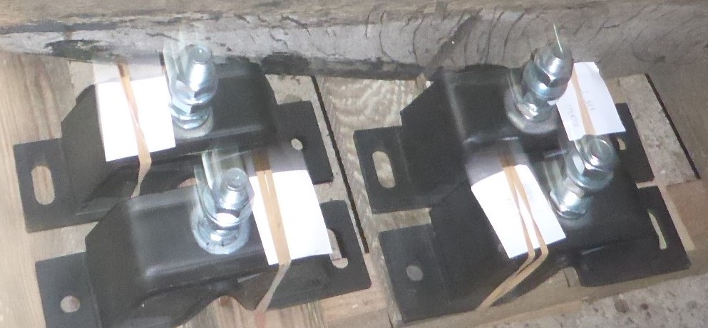
Engine mounts. Each has two bolt holes, one of which is elongated to allow some rotation (hence sideways movement). The mounts must be fitted in matching pairs. The front pair are stiffer than the rear pair.
Realignment requires the position of the engine to be changed a little. Each of the four corners of the engine can be moved in two ways:
- Up and down, by rotating the M17 nut that the engine bracket sits upon (the upper nut is there to lock the bracket down when its height is correct).
- Left and right, by loosening the all the nuts that secure the four mounts to the engine bearers and levering the engine sideways. (This does not require as much strength as it sounds!)
By means of these two adjustments, the engine position can be changed in:
- Height
- Position athwartships
- Pitch
- Yaw
Adjust the pairs of mounts (front or rear) at the same time, so that each pair ends up at about the same height. In other words, the engine should not ‘roll’.
Each change can lead to another, as shown below; perform small changes and be patient!
Correct vertical alignment seen from the side
Pitching the engine to align the flanges may require the engine to be raised all round
Correct horizontal alignment seen from above
Yawing the engine to align the flanges may require the whole engine to be moved sideways
Second phase
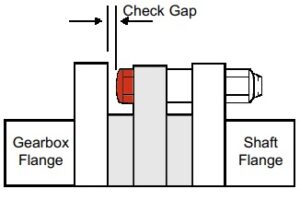
Checking the alignment with a feeler gauge (from https://www.sillette.co.uk/pdfs/RandD-shaft-flexible-coupling.pdf)
Once the bolts from the coupling are found to slide easily into the gearbox flange holes, you should install the nuts and tighten all the flange connections. There are recommended torque settings, but I found it impossible to get a torque wrench into position, so used the fall-back of making everything ‘nice and tight’. The gap is measured four times, at 90 degree intervals, and the four values should not differ by more than 0.25mm (0.1 inch). Less is better.

